
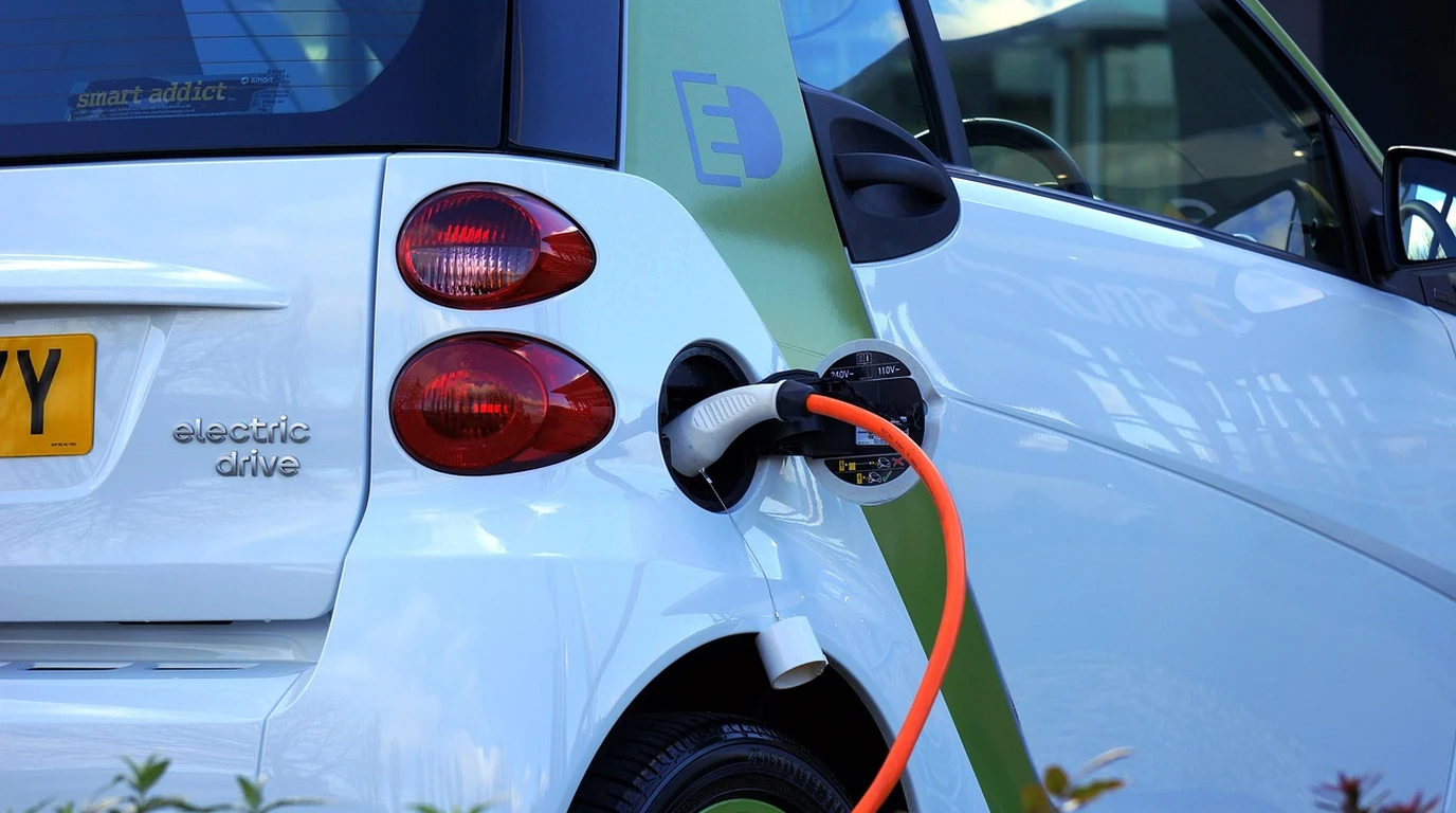
You have an electric vehicle sitting in your garage with a 70 kWh to 100+ kWh battery pack. You also have a rooftop solar array that produces clean power every single afternoon. Yet, the moment a summer thunderstorm knocks out the local power line, your house plunges into total darkness. It is one of the most frustrating paradoxes in modern electrical engineering: sitting next to a rolling power plant on four wheels while lighting candles in your living room.
Most standard EV chargers are strictly one-way street pumps—pushing alternating current (AC) into your car’s onboard converter and locking that energy inside the battery pack. Even standard Vehicle-to-Load (V2L) systems only give you a modest 120V extension cord plug off the vehicle bumper. Real resilience requires Vehicle-to-Home (V2H) capability—a setup where your electric vehicle becomes a dynamic, bidirectional generation asset capable of picking up your house’s full electrical load during a blacked-out grid.
The Enphase IQ Bidirectional EV Charger changes this dynamic entirely, but setting it up correctly requires a firm grasp of microgrid topology, communication handshakes, and high-voltage DC paths. Let’s step through how this hardware operates, where the hidden installation traps lie, and how to seamlessly integrate it with your rooftop solar array.
The Enphase IQ Bidirectional EV Charger delivers true Vehicle-to-Home (V2H) backup by connecting your EV directly via high-voltage DC to the Enphase System Controller 3/3G. Bypassing onboard AC chargers through ISO 15118-20 protocol, it seamlessly pairs with IQ8 solar microinverters to island your home during outages, providing up to 9.6 kW of continuous bidirectional backup power.
How Does the Enphase IQ Bidirectional Charger Connect to My Home?
To understand why the Enphase IQ Bidirectional EV Charger is fundamentally different from a standard Level 2 EVSE (Electric Vehicle Supply Equipment), you have to look at where the AC-to-DC conversion happens. In a standard setup, your charger supplies 240V AC power directly to the vehicle. The vehicle’s internal Onboard Charger (OBC) takes that AC power, rectifies it to high-voltage DC (typically 400V or 800V), and feeds it into the traction battery pack. Because that OBC is designed strictly as a unidirectional rectifier, it cannot invert power back out to your home panel.
The Enphase IQ Bidirectional Charger bypasses the vehicle’s internal AC charger completely during discharge modes. Instead, it interfaces directly with the vehicle’s high-voltage DC bus through a CCS1 or NACS (SAE J3400) connector. When grid power drops, the Enphase unit pulls direct current directly off the car’s battery cell strings, running that DC power into an internal microinverter matrix or direct DC bus architecture integrated with the Enphase System Controller 3 or 3G.
This high-voltage handshake relies on the ISO 15118-20 communication standard. ISO 15118-20 is the international digital protocol designed specifically for bidirectional energy transfer, enabling automated authentication, bidirectional power flows, and real-time telemetry. Over a High-Level Communication (HLC) link using HomePlug Green PHY Power Line Communication (PLC) over the control pilot pin, the EV and the Enphase charger negotiate continuous voltage levels, dynamic amp limits, thermal limits, and state-of-charge (SoC) floors before a single watt flows back toward the main distribution panel.
Inside the home, the key orchestrator is the Enphase System Controller 3/3G. This unit acts as the Intelligent Interconnection Switch (IIS) or Microgrid Interconnection Device (MID). When the utility grid fails, the System Controller opens its internal contactors to mechanically isolate your electrical system from the utility grid within milliseconds. Once isolated, it forms a local microgrid reference signal, allowing the bidirectional charger and rooftop solar microinverters to generate split-phase 120V/240V power safely without backfeeding dead utility lines.
What Are the Most Expensive Mistakes Homeowners Make with V2H Setup?
While the prospect of turning your EV into a massive 80+ kWh household battery sounds like an absolute silver bullet, jumping blindly into a V2H installation without understanding system nuances leads to expensive mistakes. Here are the four primary failure points that catch homeowners and installers off guard:
1. EV Battery Warranty Voiding and Degradation Limits: Automakers are historically conservative with battery pack cycling. Pulling heavy daily energy loads to run whole-home AC units can accelerate cell degradation if not managed intelligently. Certain manufacturers explicitly restrict V2H or Vehicle-to-Grid (V2G) power discharge under their standard battery warranty terms unless operating within specific daily energy throughput caps. System software must be configured with a strict State-of-Charge reserve floor (typically 20% to 30%) to ensure you aren’t stranded with a dead car when you need to evacuate during an emergency.
2. Round-Trip Efficiency (RTE) Losses: Moving electricity isn’t free; every conversion step incurs an energy tax. When rooftop solar panels generate DC power, microinverters convert it to 240V AC. The bidirectional EV charger converts that AC back to DC to store it in the car’s pack. When backing up the house, the car discharges DC, which the Enphase bidirectional system converts back into AC. Across this double-conversion path (AC-DC-AC), expect a system Round-Trip Efficiency between 80% and 85%. Comparatively, dedicated stationary storage systems like the Enphase IQ Battery 5P achieve slightly higher direct RTE because they operate on shorter, optimized DC/AC bus architectures within a single enclosure.
3. Neutral-Ground Bonding Loops During Microgrid Islanding: When the System Controller 3 opens the grid contactor, your electrical service transitions from a grounded utility system to an isolated islanded microgrid. The system must immediately bond neutral to ground within the System Controller to ensure fault protection devices (GFCI breakers and rapid-shutdown circuits) function safely. If an installer incorrectly maintains an active secondary neutral-ground bond down panel from the controller, ground loops will trigger nuisance trips across both the EVSE interface and vehicle contactors, locking out backup power precisely when you need it.
4. Panel Overloading and Thermal Throttling: Supplying 9.6 kW continuous power (40 Amps at 240V) places sustained thermal stress on garage electrical subpanels, wire terminations, and the vehicle’s internal thermal management system. If the garage ambient temperature spikes during a summer heatwave and blackout, the vehicle or charger may thermally throttle discharge rates down to 3.8 kW or 5.7 kW to protect thermal degradation of the lithium-ion cells.
| System Parameter | Standard Level 2 Charger | AC V2L / Basic Generator Plug | Enphase IQ Bidirectional + System Controller 3 |
|---|---|---|---|
| Power Directionality | Unidirectional (Grid-to-Vehicle) | Bidirectional (Vehicle-to-Load only) | True Bidirectional (V2H & V2G) |
| Max Discharge Power | N/A (0 kW output) | 1.9 kW – 3.6 kW (120V/240V outlet) | Up to 9.6 kW continuous (240V) |
| Microgrid & Solar Integration | None | Isolated extension cord loads only | Seamless pairing with IQ8 microinverters |
| Islanding Transfer Speed | N/A | Manual plug-in required | Automatic transition (~100ms switch-over) |
| Communication Protocol | SAE J1772 Basic PWM | Proprietary vehicle manufacturer spec | ISO 15118-20 High-Level PLC Protocol |
| Typical Round-Trip Efficiency | ~88% (Charging only) | ~75% – 80% | 80% – 85% (System-wide AC-DC-AC) |
How Does Enphase Handle Microgrid Islanding and IQ8 Solar Pairing?
The true magic of the Enphase ecosystem reveals itself when you combine the IQ Bidirectional Charger with rooftop IQ8 series microinverters. Legacy microinverters or string inverters require an active external AC reference signal from the electric grid to function. When the grid dies, standard solar systems immediately shut down to satisfy anti-islanding regulations under IEEE 1547. If you have an ordinary solar setup during a blackout, those panels are rendered useless.
Enphase IQ8 microinverters possess dynamic grid-forming capability. Using high-speed digital signal processors (DSPs), they can form their own stable AC microgrid without relying on the utility grid. When paired with the Enphase System Controller 3 and the IQ Bidirectional Charger, a fully orchestrated energy triangle is established:
- The Grid Anchor: During an outage, the EV’s massive traction battery acts as the primary microgrid anchor (a large, stable energy reservoir). The Enphase System Controller manages frequency and voltage control for the islanded home.
- Solar Generation & Dynamic Throttle: IQ8 microinverters generate power from rooftop sunlight to serve live household loads. If total solar production exceeds current household consumption, the excess power is directed down the bidirectional charger into the EV’s battery pack, recharging your vehicle for free during a blackout.
- Frequency Shifting & Digital Control: If the EV battery reaches 100% capacity while solar generation still exceeds household demand, the System Controller shifts the islanded microgrid’s operating frequency (raising it slightly from 60.0 Hz toward 62.0 Hz) or uses local CAN bus/Ethernet controls to modulate or gracefully ramp down IQ8 production. This balance prevents over-voltage conditions across home circuits without hard-tripping system breakers.
- Load Management: Using Enphase IQ Load Controllers, non-essential heavy circuits (such as electric pool heaters, hot tubs, or secondary air handlers) are automatically shed during grid failures. This ensures the continuous load never exceeds the 9.6 kW threshold of the charger or the discharge limits of the vehicle’s traction battery.
How Do You Install and Configure Enphase V2H Step-by-Step?
Setting up an Enphase IQ Bidirectional Charger and integrating it for full V2H microgrid isolation requires structured execution. Follow this installation playbook to ensure seamless operation and code compliance:
Step 1: Perform Electrical Service & Load Calculation
Audit your main service panel. Calculate continuous loads using NEC Article 220 rules. Determine whether the system will utilize Whole-Home Backup or Partial-Home Backup via a dedicated Critical Loads Subpanel. Ensure the total maximum continuous discharge from the EV (9.6 kW / 40A at 240V) does not exceed your intended subpanel rating or busbar capacity.
Step 2: Install the Enphase System Controller 3 or 3G
Mount the System Controller 3 between the main utility meter socket and your distribution panels. Secure the Microgrid Interconnection Device (MID) contactors. Establish the main system bonding jumper inside the System Controller to ensure clean neutral-ground framing during islanded operation. Connect the neutral framing transformer circuit where required by localized split-phase configurations.
Step 3: Run High-Voltage Interconnect & Wire Infrastructure
Pull 600V-rated THHN/THWN-2 copper conductors from the System Controller’s dedicated EVSE breaker slot to the garage mounting location. Install a 50A or 60A double-pole breaker depending on output configuration. Crucially, pull a shielded twisted-pair CAT6 cable for control bus communications alongside the power conductors to establish a hardwired local control connection between the System Controller, Enphase Gateway, and the charger.
Step 4: Mount and Wire the IQ Bidirectional EV Charger
Securely mount the Enphase IQ Bidirectional Charger to garage framing studs. Terminate the AC output/input leads, ground fault monitoring conductors, and the control bus lines into the unit chassis. Connect the heavy-duty CCS1 or NACS cable assembly to the charger faceplate.
Step 5: Provision Firmware and ISO 15118-20 Communication Profiles
Open the Enphase Installer App (formerly Installer Toolkit). Scan the QR codes for the System Controller 3, Gateway, IQ8 microinverters, and the Bidirectional EV Charger. Commission the ISO 15118-20 communications profile. Map your specific EV model parameters, granting authorization for high-voltage DC discharge and setting battery parameters.
Step 6: Configure Software Reserve Limits & Perform Blackout Testing
In the Enphase App user interface, set the EV Discharge Reserve Floor (e.g., set to 25% or 50 miles of driving range reserve). Schedule Time-of-Use (TOU) arbitrage parameters if applicable. Finally, perform an actual functional test: open the utility main breaker at the service entrance. Verify that the System Controller disconnects from the grid in milliseconds, the microgrid forms, the EV initiates high-voltage DC discharge via ISO 15118-20, and the rooftop solar array continues producing power uninterrupted.
| Hardware Component | Electrical Specification | Wiring / Interconnect Requirement | Key Function in V2H Ecosystem |
|---|---|---|---|
|
Bidirectional Charging Protocols & Stationary Power
Evaluating mobile EV battery capacity against dedicated stationary storage requires clear balance-of-system cost accounting. Examine our teardown on V2H vs Home Batteries: Ford F-150 Lightning vs Powerwall. |