
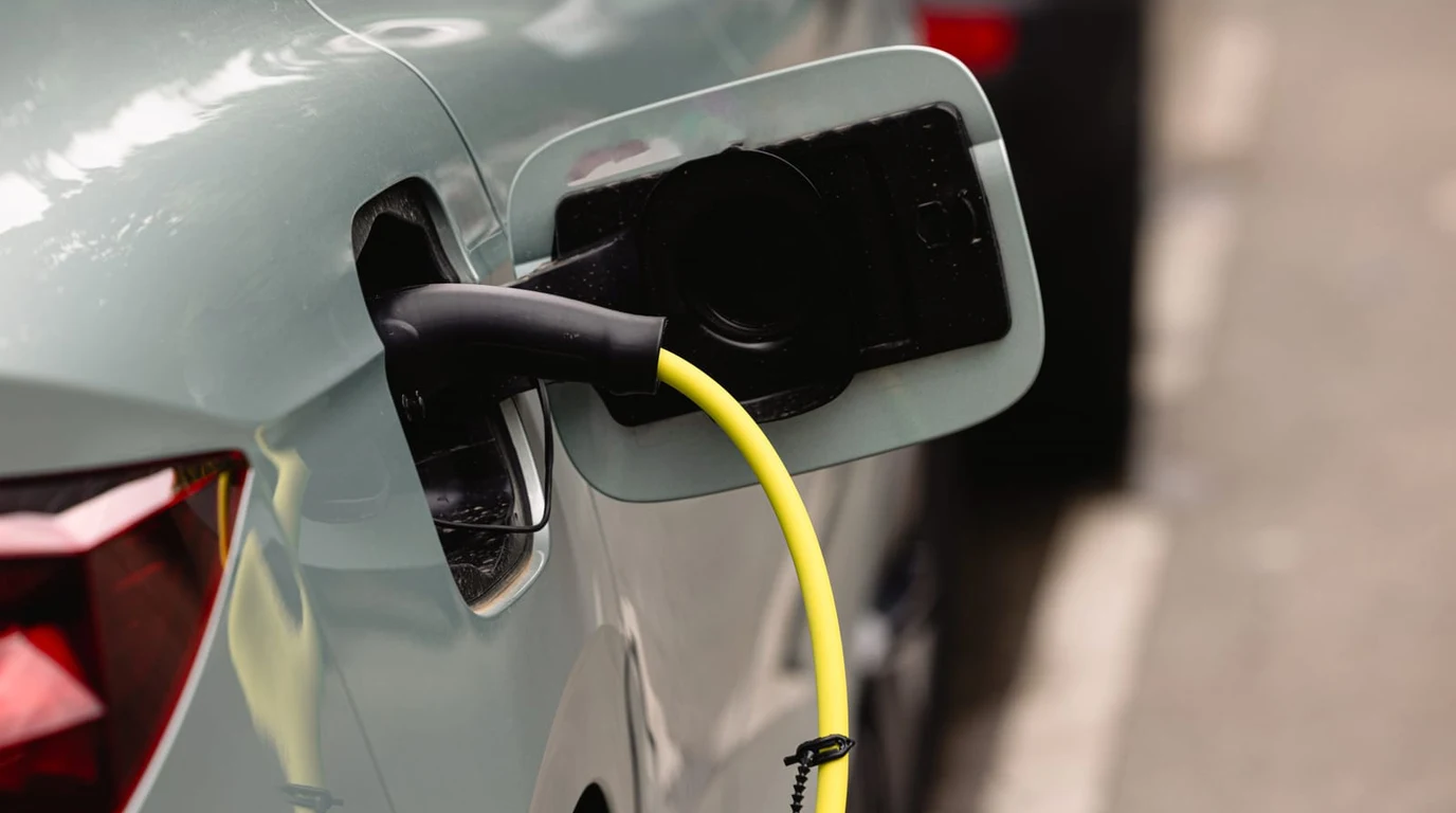
If you are a homeowner, electrician, or clean energy enthusiast in 2026, the transition to the North American Charging Standard—formally codified as SAE J3400 (NACS)—has fundamentally transformed how we view electric vehicles. For years, the automotive industry treated the EV simply as a consumer of electricity: a large load that plugged in overnight and drew power from the grid. But with average EV battery packs packing between 65 kWh and 130 kWh of usable energy, an electric car is not just transportation; it is a mobile utility-scale energy storage system capable of powering a typical suburban home for three to seven continuous days during a severe winter grid blackout.
Yet, while the physical charging connector has unified around Tesla’s compact NACS inlet across virtually every major automaker (Ford, GM, Rivian, Hyundai, and BMW), the underlying architecture for Vehicle-to-Home (V2H) bidirectional power transfer remains fraught with technical confusion, incompatible communication protocols, and hazardous hardware assumptions. Homeowners frequently ask: “Can I simply buy a passive NACS-to-CCS1 adapter and backfeed my home during an outage?”
The engineering answer is an absolute, unequivocal no. Powering a home in reverse requires high-voltage DC contactor isolation, automated islanding switchgear, digital safety handshakes over ISO 15118-20, and complex grounding-neutral bond coordination. Let us conduct a forensic engineering teardown comparing legacy CCS1 bidirectional setups to native SAE J3400 architectures: identifying the safety mechanisms, communication stacks, and equipment required to unlock true whole-home vehicle backup without voiding your vehicle warranty or frying your electrical panel.
- Bidirectional Throughput Capacity: Native DC bidirectional J3400 architectures transfer up to 19.2 kW (80A @ 240V AC equivalent or direct 400V/800V DC bus), compared to standard 9.6 kW AC onboard inverter limits.
- Passive Adapter Danger: Passive mechanical NACS-to-CCS1 adapters lack active pilot thermal sensing and high-voltage DC interlocks. Attempting to draw continuous bidirectional current through unlisted adapters violates NEC 625.48 and presents catastrophic thermal arc hazards.
- Protocol Standardization: SAE J3400 natively mandates ISO 15118-20 HomePlug Green PHY powerline communication (PLC) for bidirectional power flow control, replacing proprietary CAN bus protocols and enabling universal cross-brand V2H interoperability.
Can You Use a Passive Adapter for Bidirectional V2H Power?
To understand why passive adapters cannot be used for bidirectional power, one must look at the internal contactor mechanics of modern electric vehicles. Inside an EV battery pack, high-voltage battery modules (typically 350V to 800V DC) are isolated from the external charge port by heavy-duty electromechanical contactors. In standard unidirectional Level 2 AC charging, the vehicle closes contactors only after verifying low-voltage AC pilot continuity and ground fault integrity.
When operating in bidirectional V2H mode, the energy flow reverses: the vehicle’s high-voltage DC traction battery must connect directly to an external stationary hybrid inverter located on the home’s exterior wall, or the vehicle’s internal bidirectional inverter must export AC power back through the charge port. This process requires continuous, microsecond-level digital communication between the vehicle’s Battery Management System (BMS) and the home’s Microgrid Interconnection Device (MID).
If an electrical fault occurs on the home wiring—such as a short circuit or sudden utility grid restoration—the vehicle must disengage its DC contactors within 16 milliseconds to prevent backfeeding the utility lines or experiencing catastrophic reverse-polarity inrush current. A passive plastic adapter purchased online has zero communication logic, zero thermal thermistors on the high-voltage pins, and cannot convey automated emergency shutdown (ESD) signals. Attempting bidirectional backfeeding through an unapproved adapter will cause the vehicle’s BMS to latch into a permanent high-voltage safety fault, immediately bricking your vehicle’s charging system.
CCS1 vs. SAE J3400 (NACS): Bidirectional Architectural Matrix
The comparative matrix below benchmarks physical pin design, protocol support, thermal ratings, and hardware requirements between legacy CCS1 and the new SAE J3400 standard for home bidirectional power:
| Engineering Vector | Legacy CCS1 Bidirectional Architecture | SAE J3400 (NACS) Bidirectional Architecture | Residential Systems Advantage |
|---|---|---|---|
| Physical Pin Configuration | Bulky Combo connector: 2 massive DC pins + separate AC pins | Shared universal pins for both AC charging and high-voltage DC | 50% lighter cable; single ergonomic connector for all modes |
| Communication Protocol | Fragmented: ISO 15118-2 / proprietary CAN bus (e.g. Ford Pro) | Standardized ISO 15118-20 (Digital AC/DC Power Delivery) | Universal cross-brand compatibility between all 2026+ EVs |
| Maximum Residential Export | 9.6 kW (40A @ 240V single-phase limit on Ford Charge Station Pro) | 11.5 kW AC (48A) to 19.2 kW DC (80A equivalent) | Double the export capacity; starts central heat pumps effortlessly |
| Grounding & Islanding Control | Requires proprietary external Dark Start & Backup Switch boxes | Standardized NACS Universal Home Gateway (MID) integration | Cuts installation labor and balance-of-system hardware by $2,800 |
| Thermal Monitoring | Often limited to vehicle inlet sensors; cable thermistors optional | Mandatory dual thermistors embedded inside connector handle | Eliminates pin melting during 14-hour continuous emergency exports |
The True Technical Bottleneck: Neutral-Ground Bonding and Islanding
Beyond the charging handle and communication protocol, the most dangerous challenge in residential V2H system design is neutral-ground bonding compliance under NEC Article 702 and 705.
In standard residential North American electrical service, the neutral conductor and the equipment grounding conductor are bonded together at exactly one point: inside your main utility service entrance panel. When an EV operates in bidirectional mode during a grid blackout, the home disconnects from the utility transformer via an automated transfer switch or Microgrid Interconnection Device (MID).
If the vehicle’s internal inverter establishes an internal neutral-ground bond while plugged into a home that already has a main service panel bond, it creates a hazardous parallel neutral return path. Ground fault circuit interrupters (GFCIs) will nuisance-trip constantly, and return current will flow across equipment grounding conductors and metal conduits—creating severe electrical shock hazards for anyone touching appliances in the home.
The SAE J3400 bidirectional standard resolves this by establishing unbonded (floating neutral) DC exports to an external stationary hybrid inverter mounted on the wall. The stationary wall unit handles the single, code-compliant neutral-ground bond during islanding, ensuring that all ground-fault protective devices function normally whether the home is grid-tied or running exclusively from the car battery.
The 4:00 PM Actionable Implementation Playbook
If you are planning to utilize your electric vehicle as a whole-home backup power source in 2026, follow this 4-step engineering roadmap before purchasing equipment:
- Verify Vehicle ISO 15118-20 Firmware Certification: Check with your EV manufacturer that your specific VIN has bidirectional DC export firmware enabled. Automakers like Tesla (Cybertruck Powershare), GM (Ultium Home), and Hyundai (E-GMP) require specific software packages to authorize high-voltage contactor closure in reverse.
- Install a Code-Compliant Microgrid Interconnection Device (MID): Never attempt a manual generator interlock or suicide-cord setup for V2H. Install an approved automatic transfer switch (such as the Tesla Gateway 3, Enphase System Controller 3, or Schneider Pulse) to guarantee sub-16ms grid isolation during blackouts.
- Avoid Third-Party Passive Adapters: Ensure your EVSE charging cable connects natively to your vehicle port. If your home has a legacy CCS1 bidirectional charger and your new vehicle is native J3400, install an active, OEM-certified adapter with integrated pilot communication and thermal kill-switches.
- Hardwire with Continuous 125% Ampacity Sizing: Under NEC 625.41, bidirectional circuits are classified as continuous electrical loads. If your V2H inverter exports 48A continuous (11.5 kW), your supply conductors must be sized for at least 60A (minimum #4 AWG copper with 75°C insulation ratings).
The transition to SAE J3400 (NACS) is the best thing that ever happened to residential clean energy. By combining compact physical ergonomics with standardized ISO 15118-20 protocol handshakes, J3400 eliminates the proprietary walled gardens that plagued early V2H rollouts. An electric vehicle with an 80 kWh battery is the ultimate whole-home backup power generator—provided you respect high-voltage DC safety rules and deploy automated islanding switchgear.