
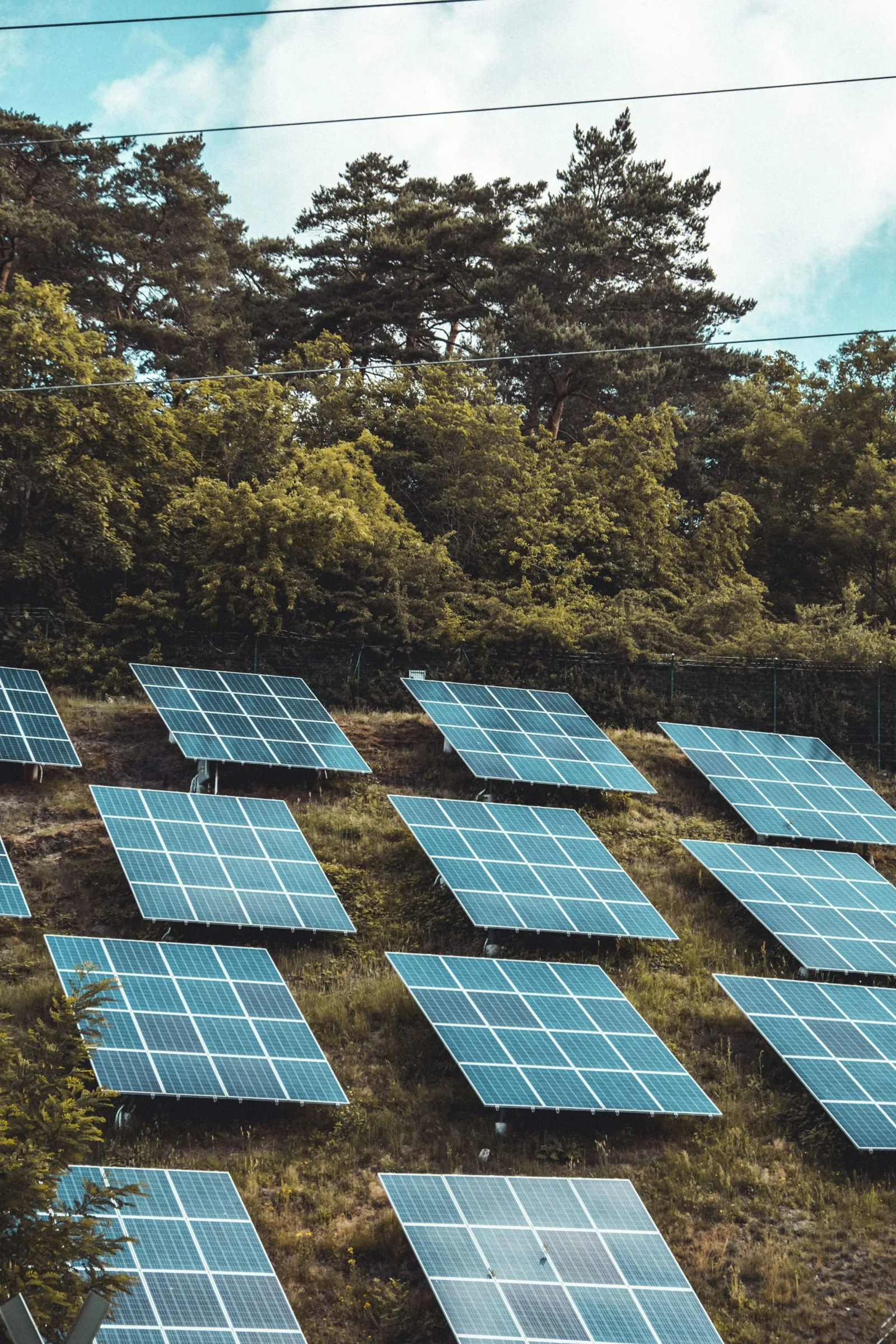
- The 1:1 Sizing Myth: Matching a 10 kW DC solar array with a 10 kW AC inverter is an economic and thermodynamic mistake. Due to thermal derating, dirt/soiling, wire resistance, and solar irradiance curves, an array rarely produces its STC (Standard Test Conditions) nameplate power.
- The Golden Inverter Loading Ratio (ILR): Modern solar engineering targets an Inverter Loading Ratio between 1.20 and 1.35 (e.g., pairing 12.5 kW DC of solar modules with a 10 kW AC inverter).
- Clipping Loss vs. Shoulder Gain: While deliberate oversizing causes clipping during midday summer peaks (losing 1–2% of total theoretical energy), it dramatically widens morning and late afternoon generation “shoulders” and captures significantly more kWh during overcast days, boosting total annual energy yield by 8–15%.
When prospective solar buyers review system proposals, discovering that a 12 kW solar panel array is paired with a 9.6 kW inverter often sparks panic. Homeowners assume the installer is cutting corners or throttling their equipment. In reality, oversizing the DC solar array relative to the AC inverter nameplate is standard best practice in utility-scale and residential photovoltaic engineering.
Operating an inverter at an optimized Inverter Loading Ratio (ILR) ensures the inverter operates in its peak conversion efficiency curve (typically 40% to 90% load) throughout early morning, late afternoon, and winter months.
Why Do Solar Installers Oversize the DC Array Relative to the Inverter?
Examine the mathematical mechanics of oversizing in our analysis on Solar Inverter Clipping: Why DC-to-AC Oversizing Pays, and evaluate advanced module architectures in Bifacial Solar Panels: Albedo Ground Reflection Guide.
Inverter Loading Ratio (ILR) Financial & Energy Comparison Matrix
The comparative matrix below illustrates annual production, clipping loss, and economic return across different DC-to-AC sizing ratios for a 10 kW AC inverter system:
| DC Array Size (STC) | DC:AC Ratio (ILR) | Clipping Loss (% Annual) | Low-Light Shoulder Gain | Levelized Cost of Energy (LCOE) |
|---|---|---|---|---|
| 10.0 kW DC | 1.00 (1:1 Ratio) | 0.0% (Zero clipping) | Baseline (Poor low-light conversion) | Highest (Inverter capacity underutilized 85% of time) |
| 11.5 kW DC | 1.15 (Mild Oversizing) | <0.5% (Negligible) | +6.2% shoulder energy boost | Moderate reduction |
| 12.8 kW DC | 1.28 (Sweet Spot) | 1.2% – 1.8% | +14.5% shoulder & cloudy day boost | Optimal (Lowest LCOE per generated kWh) |
| 14.5 kW DC | 1.45 (Heavy Oversizing) | 4.5% – 6.0% | +21.0% low-light harvest | Economical only with battery DC-coupling or steep panel discounts |
The Physics of Inverter Clipping: Why Clipping Does Not Harm Hardware
A common misconception is that inverter clipping “strains” or “burns out” the inverter by forcing it to absorb excess power. In reality, modern inverters control DC input current dynamically using Maximum Power Point Tracking (MPPT) algorithms.
When available DC solar power exceeds the inverter’s maximum AC processing limit, the MPPT simply shifts the module operating voltage along the IV curve away from the maximum power point toward the open-circuit voltage ($V_{oc}$). The extra energy is simply not extracted from the solar panels; it remains unabsorbed as ambient light reflection and slight heat, with zero stress placed on internal inverter silicon.
Never fear a flat-topped solar generation curve during noon on a summer solstice. An Inverter Loading Ratio of 1.25 to 1.30 delivers substantially superior financial ROI and overall energy production compared to a conservative 1:1 ratio. Designing for morning, afternoon, and winter shoulder harvest is the hallmark of professional clean energy engineering.