
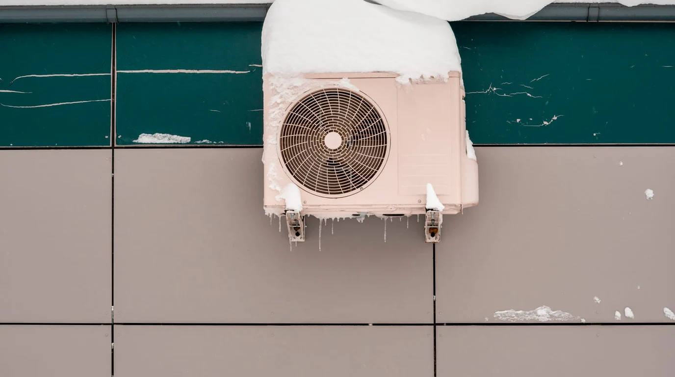
In cold-climate heat pump engineering, the most thermodynamically punishing operational window does not occur during bone-chilling subzero conditions at -15°F (-26°C)—it occurs between 28°F and 38°F (-2.2°C to 3.3°C) under conditions of high ambient relative humidity. In this temperature band, outdoor air contains abundant moisture vapor. As the outdoor fan draws humid air across evaporator coils operating below freezing (typically 10°F to 15°F below ambient), moisture instantaneously freezes, coating the aluminum micro-channel fins in dense frost.
Left unchecked, frost acts as an insulating thermal blanket, choking off airflow and causing suction pressure to collapse. To restore heat transfer, the heat pump must periodically reverse its thermodynamic cycle, transforming the outdoor unit into a temporary air conditioner to melt the ice. This reverse-cycle defrost consumes significant electrical power, causes indoor temperature dips (‘cold blow’), and imposes a severe penalty on seasonal Coefficient of Performance (COP). In this technical teardown, we audit defrost control algorithms, auxiliary heat strip staging, and modern strategies to mitigate seasonal efficiency drag.
- Seasonal COP Penalty: Defrost cycling degrades nominal steady-state COP by 12% to 18% in damp coastal and temperate winter climates between 30°F and 40°F.
- Demand vs. Timed Defrost: Modern optical and differential-temperature demand defrost systems reduce energy consumption by up to 35% compared to crude 30/60/90-minute mechanical timer boards.
- Auxiliary Strip Lockout: Staging electric resistance strips during defrost prevents indoor draft complaints but spikes household electrical demand by 5 kW to 10 kW.
How Does a Heat Pump Reverse-Cycle Defrost Work?
The sequence of operations during a modern reverse-cycle defrost is a tightly orchestrated thermodynamic dance. When sensors detect frost saturation on the outdoor coil, the micro-controller initiates the following steps:
- Compressor Down-Ramp & Valve Shift: The variable-speed compressor slows down to equalize system pressures, and the 4-way reversing valve shifts, reversing refrigerant flow. Hot high-pressure discharge gas from the compressor bypasses the indoor coil and heads straight into the frosted outdoor coil.
- Outdoor Fan Shutdown: The outdoor fan motor is instantly depowered. If the fan continued spinning, freezing ambient air would carry away the heat, slowing down ice melt. Shutting the fan off concentrates thermal energy inside the coil core.
- Indoor Auxiliary Heat Staging: Because the heat pump is now operating in air conditioning mode, the indoor air handler coil becomes the evaporator, pulling heat out of the home. To prevent 45°F (7°C) refrigerated air from blowing out of ceiling registers, the control board energizes auxiliary electric resistance heat strips (typically 5 kW to 10 kW) to reheat the supply air.
- Defrost Termination: Once an outdoor coil temperature thermistor reads between 55°F and 65°F (12.7°C to 18.3°C), verifying that all ice has melted into water and drained off, the reversing valve shifts back to heating, the outdoor fan starts, and normal heating resumes.
Timed Defrost vs. Demand Defrost Logic: Energy Comparison
The table below compares the efficiency, sensor architectures, and seasonal COP drag between legacy timed defrost boards and modern micro-controller demand defrost systems:
| Defrost Control Architecture | Trigger Sensor Mechanism | False Defrost Cycle Risk | Seasonal Efficiency Impact |
|---|---|---|---|
| Time-and-Temperature (Legacy) | Simple timer pin (30/60/90 min) + bi-metal thermostat | High (Defrosts dry coils on sunny days) | Severe 15% – 20% seasonal COP penalty |
| Differential Temperature (Modern) | Dual thermistors (Coil temp vs Ambient outdoor air) | Low (Triggers only when delta-T widens from frost) | Mild 6% – 8% seasonal COP drag |
| Pressure-Drop / Airflow Sensor | Static pressure differential transducer across coil | Extremely low (Measures actual airflow blockage) | Optimal efficiency; zero wasted defrost energy |
The ‘Cold Blow’ and Auxiliary Heat Strip Penalty
The single greatest operational friction during defrost is auxiliary resistive heat strip engagement. A standard residential heat pump requires roughly 5 kW to 10 kW of electric strip heat to temper the 500 to 1,200 CFM of refrigerated air circulating through ductwork while the heat pump runs in reverse cooling mode.
Because electric resistance heat operates with a fixed COP of exactly 1.0 (1 watt of electricity = 3.412 BTUs of heat), energizing 10 kW of heat strips for 8 minutes every 45 minutes spikes household electrical demand and devours operating budgets. In advanced inverter heat pump systems, proprietary communicative algorithms modulate compressor speed dynamically during defrost, minimizing defrost runtimes to under 3 to 4 minutes and slashing auxiliary strip runtimes by over 70%.
Cold-Climate Engineering: Elevation and Drainage Strategies
Even the most sophisticated defrost algorithm will fail if physical site installation ignores basic hydrology. When an outdoor unit defrosts, it dumps 1 to 3 gallons of liquid water off the coil in under 5 minutes. In sub-freezing weather, that water hits the ground and instantly freezes.
- Elevation Brackets: An outdoor heat pump must be mounted on heavy-duty wall brackets or elevated ground snow stands at least 12 to 18 inches above the local historic 100-year snowpack level. If the unit sits flush on a concrete slab, refrozen meltwater accumulates beneath the unit, forming an ice dam that creeps into the lower aluminum fins, crushing the refrigerant tubing and causing catastrophic freon leaks.
- Pan Heaters with Smart Thermostats: In extreme climates, outdoor drain pan freeze-up is prevented by installing a low-wattage (40W to 80W) electric heating cable in the bottom drain tray. To avoid energy waste, choose smart heating cables that only energize when outdoor temperatures drop below 32°F (0°C) and the unit enters defrost mode.
Thermodynamic Enthalpy Recovery and Continuous Heating Cycles
To eliminate the COP penalty and cold-blow draft issues inherent to standard reverse-cycle defrost, advanced HVAC manufacturers have engineered alternative thermodynamic defrost topologies. Foremost among these is continuous-heating hot-gas bypass architecture and split dual-circuit outdoor coils (pioneered in high-end cold-climate systems such as Mitsubishi Hyper-Heating and Daikin VRV platforms).
In a dual-circuit outdoor coil system, the outdoor heat exchanger is divided into two hydraulically independent upper and lower circuits. When frost accumulation triggers a defrost requirement, the system modulates electronic expansion valves (EEVs) to divert hot refrigerant gas to only one coil circuit at a time. The active coil circuit continues absorbing thermal energy from ambient outdoor air and providing continuous heated air to indoor living spaces, while the alternate circuit rapidly melts its frost layer in under two minutes.
This staggered, split-circuit defrost architecture completely eliminates the requirement for auxiliary electric resistance heat strips during defrost cycles. Household power draw remains capped at the standard compressor operating wattage (typically 1.5 kW to 3.0 kW) rather than spiking to 10 kW. By eliminating electric strip auxiliary staging and maintaining continuous indoor comfort, continuous-heating heat pumps maintain seasonal real-world COP ratings above 2.8 even in the most frost-prone coastal winter environments.
Subzero heating performance is intrinsically tied to reverse-cycle defrost intervals. Cross-reference our forensic analysis on defrost COP degradation: Cold-Climate Heat Pump COP at -30C: R-454B vs R-32 Test.