
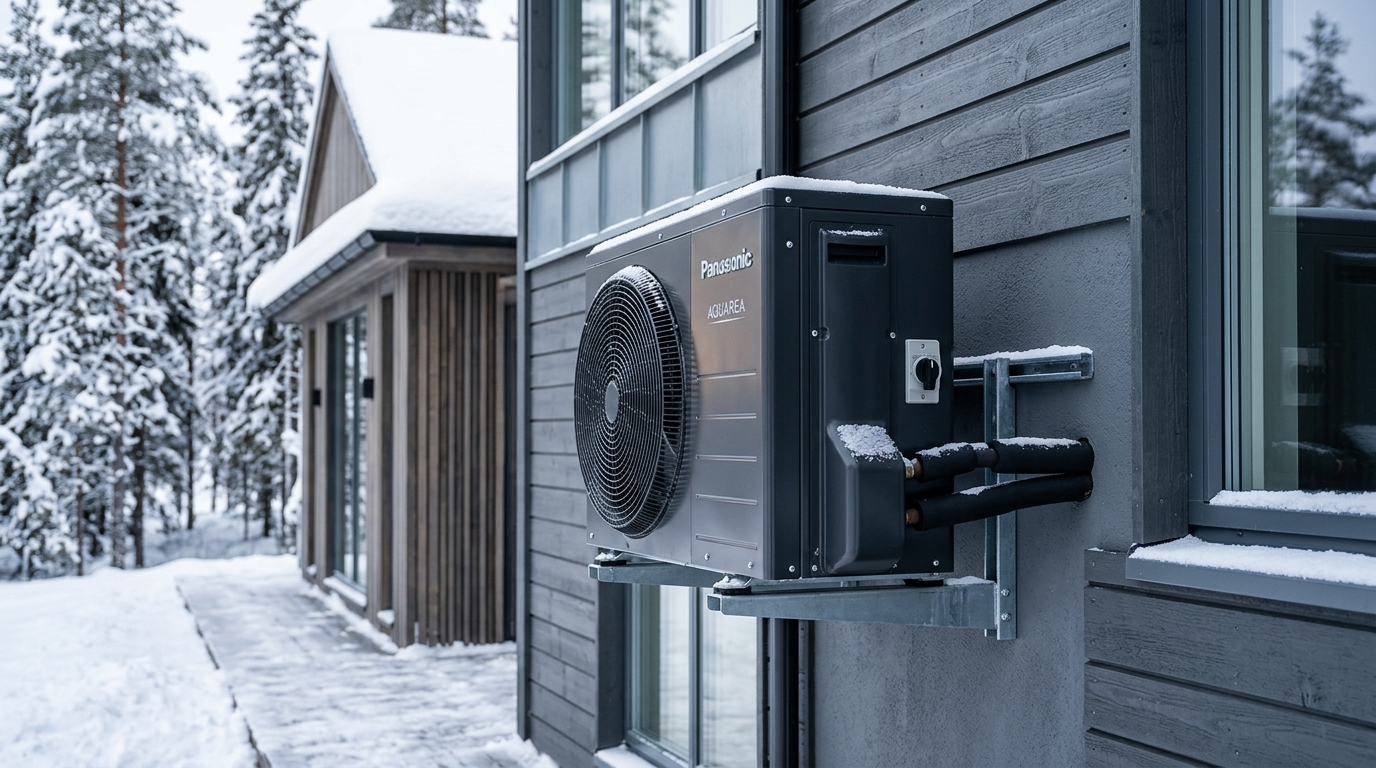
- The Sub-Zero Thermodynamic Barrier: Conventional single-stage air-source heat pumps suffer steep volumetric efficiency collapses below -10°C (14°F) as refrigerant vapor density plummets. True cold-climate performance requires variable-speed rotary or scroll compressors equipped with Enhanced Vapor Injection (EVI) or flash-tank subcooling, maintaining full rated thermal output down to -15°C and operational stability at -25°C (-13°F) and lower.
- Real-World Sub-Zero COP: While manufacturer marketing highlights laboratory Coefficients of Performance (COP) exceeding 3.8 at +8.3°C (47°F), empirical field logging demonstrates real-world COPs degrading to 1.85 to 2.15 at -15°C and 1.45 to 1.70 at -25°C. Even at 1.50 COP, the heat pump delivers 50% more thermal kilowatt-hours per unit of electricity than pure resistive auxiliary strip heat.
- The Thermal Balance Point & Backup Dynamics: In northern climate zones (ASHRAE Climate Zones 5 through 7), oversizing heat pump tonnage to meet 100% of peak sub-zero heating load causes severe short-cycling and dehumidification failure during shoulder seasons. The engineering gold standard is precise sizing to building balance points (-8°C to -12°C), paired with staged low-watt-density electric elements or dual-fuel condensing gas hydronic backup.
- The Defrost Cycle Parasitic Penalty: Peak frosting occurs between -2°C and +3°C under high relative humidity (>85% RH), forcing periodic 4-to-8 minute reverse-cycle defrosts that consume compressor and supplemental energy. Cold-climate architectures must deploy microchannel defrost sensors and basepan de-icing heaters to prevent ice bridging.
Across North America and northern Europe, residential heating electrification represents the single largest decarbonization vector for the modern grid. Yet, for millions of homeowners and building operators in cold climates, transitioning away from fossil natural gas, heating oil, or propane remains shadowed by persistent skepticism: Can an air-source heat pump reliably warm a home when outdoor ambient temperatures plunge to -25°C (-13°F) without astronomical electric bills?
The short answer is yes—but only through rigorous mechanical system design. The physics governing cold climate heat pump subzero efficiency cannot be circumvented with software tuning or generic inverter compressors. Navigating severe winter conditions requires understanding vapor-injection thermodynamics, empirical Coefficient of Performance (COP) degradation curves, thermal balance points, and the parasitic loads of defrost cycles. This teardown deconstructs cold-climate heat pump engineering to deliver the mathematical and mechanical realities of sub-zero heating.
1. The Thermodynamic Wall: Carnot Limitations at Deep Sub-Zero
A heat pump does not generate thermal energy; it absorbs existing ambient heat from outside air across an evaporator coil, elevates that thermal energy to a higher temperature level via mechanical vapor compression, and rejects it into the interior living space across a condenser coil. This vapor-compression refrigeration cycle operates under the fundamental limits of the second law of thermodynamics.
The theoretical maximum efficiency of this cycle is dictated by the Carnot Coefficient of Performance for heating:
Where temperatures are expressed in Kelvin. As outdoor ambient air (T_outdoor) drops from +10°C (283 K) to -25°C (248 K) while maintaining an indoor delivery setpoint of +21°C (294 K), the thermal lift (temperature differential) widens from 11 K to 46 K. The Carnot ceiling drops proportionally from 26.7 down to 6.39. In physical systems subject to fluid friction, motor losses, and isentropic compressor inefficiency, real-world COPs represent roughly 25% to 35% of the Carnot ideal.
At -25°C, conventional single-stage air-source heat pumps hit a catastrophic mechanical wall:
- Suction Density Collapse: Cold air contains less thermal mass per cubic meter. As the evaporation temperature drops to -30°C to extract heat from -25°C air, the specific volume of the suction vapor expands dramatically. The density of entering vapor plunges, meaning the compressor cylinder sweeps very little actual refrigerant mass per rotation.
- Mass Flow Starvation: Because heating output (Q) equals refrigerant mass flow rate (m_dot) multiplied by enthalpy change (Δh), starving the compressor of mass flow causes heating capacity to drop off a cliff—frequently collapsing by 60% to 75% relative to rated capacity at +8.3°C.
- Extreme Compression Ratios & Thermal Overheating: The ratio of discharge pressure (condensing) to suction pressure (evaporating) expands from a benign 3:1 in mild weather to over 9:1 or 12:1 at -25°C. This extreme compression ratio generates soaring discharge gas temperatures (>115°C / 240°F), degrading compressor lubricating oil and triggering thermal limit shutoffs.
2. The Mechanical Solution: Enhanced Vapor Injection (EVI) & Flash Tanks
To bypass the mass flow collapse and prevent discharge overheating, cold-climate heat pump manufacturers (such as Mitsubishi Electric Hyper-Heating / H2i, Daikin Aurora, Fujitsu Halcyon XLTH, and LG RED) engineer multi-port vapor injection architectures.
The foundational technology is Enhanced Vapor Injection (EVI), implemented via an economizer plate heat exchanger or an intermediate flash tank circuit:
- Subcooling Split: High-pressure liquid refrigerant leaving the indoor condenser coil is split into two streams. The primary high-pressure stream flows through an economizer heat exchanger on its way to the outdoor expansion valve.
- Intermediate Flash Expansion: A secondary micro-stream (roughly 15–25% of total mass flow) is tapped off and expanded through an electronic expansion valve (EEV) to an intermediate pressure level, cooling it to a cold saturated vapor state.
- Economizer Subcooling: This chilled intermediate vapor passes through the other side of the economizer, dramatically subcooling the primary liquid stream before it enters the outdoor evaporator. Greater subcooling significantly increases the enthalpy difference (Δh) available in the outdoor evaporator coil, allowing it to harvest substantially more heat from sub-zero air.
- Mid-Stage Port Injection: The warmed, vaporized secondary stream is then injected directly into an intermediate port of the scroll or twin-rotary compressor during the middle of its compression stroke. This two-stage internal compression cools the compression chamber from within, keeping discharge temperatures well within safe lubricant operating thresholds while increasing the total circulating mass flow through the condenser by up to 30%.
3. Empirical COP & Heating Capacity: Field Logging vs. NEEP Lab Data
The Northeast Energy Efficiency Partnerships (NEEP) Cold Climate Air Source Heat Pump (ccASHP) specification provides the industry benchmark for testing cold-ambient machinery. Under NEEP criteria, a system must maintain a COP of at least 1.75 at -15°C (5°F) at maximum capacity and deliver at least 70% of its rated 8.3°C (47°F) heating capacity at -15°C.
The table below illustrates the thermodynamic progression of a high-performance 3-ton (36,000 BTU/hr) cold-climate vapor-injection system versus a standard builder-grade heat pump across outdoor ambient temperature bands:
| Outdoor Ambient Temp | Standard Heat Pump COP | Standard Heat Pump Capacity (BTU/hr) | Cold-Climate EVI Heat Pump COP | Cold-Climate EVI Capacity (BTU/hr) | % Rated Capacity Retained |
|---|---|---|---|---|---|
| +8.3°C (47°F) — AHRI Rated | 3.85 | 36,000 | 4.10 | 38,500 | 100% |
| 0.0°C (32°F) — Freezing Point | 2.80 | 27,500 | 3.25 | 38,000 | 99% |
| -8.3°C (17°F) — Standard Low | 2.10 | 21,000 | 2.65 | 37,200 | 97% |
| -15.0°C (5°F) — NEEP Cold Rating | 1.45 | 13,800 | 2.05 | 36,000 | 94% |
| -20.0°C (-4°F) — Deep Freeze | 1.15 (Near Lockout) | 9,200 | 1.78 | 31,800 | 83% |
| -25.0°C (-13°F) — Extreme Sub-Zero | Lockout / Strips Only | 0 | 1.55 | 27,400 | 71% |
| -30.0°C (-22°F) — Arctic Threshold | Lockout | 0 | 1.32 | 21,600 | 56% |
4. Sizing Calculations: The Balance Point Dilemma & Auxiliary Strip Penalties
The central engineering challenge in cold-climate electrification is the divergence between building heating load and heat pump heating capacity. As outdoor temperatures fall, a home’s heat loss increases linearly in direct proportion to the delta between indoors and outdoors (conductive and infiltration losses calculated via ACCA Manual J). Simultaneously, the heat pump’s maximum thermal output gently declines.
The point at which the building’s heating requirement exactly matches the heat pump’s maximum capacity is the Thermal Balance Point. Above this temperature, the heat pump delivers 100% of heating needs with zero backup. Below this temperature, supplemental heat must make up the deficit.
This introduces the primary architectural design trade-off:
- 100% Electrification with Resistive Strips: The heat pump is sized to meet load down to roughly -10°C to -15°C. When ambient temps plunge to -25°C, electric resistance heating strips (COP = 1.0) cycle on in stages (typically 5 kW, 10 kW, or 15 kW elements). While capital cost is moderate, electric strip heat draws enormous instantaneous electrical power (10 kW = 41.6 Amps at 240V). In regions with peak-demand time-of-use (TOU) rates, running 10–15 kW of auxiliary strips during sub-zero polar vortex events can cause monthly electricity bills to spike by $300 to $600.
- Dual-Fuel Hybrid System (Heat Pump + Condensing Gas): An inverter cold-climate heat pump is paired with a 96%+ AFUE two-stage or modulating natural gas/propane furnace. An outdoor thermostat or intelligent controller switches the system over to fossil heat precisely at the Economic Balance Point—the exact temperature where the cost per delivered therm of gas becomes cheaper than the cost per therm of heat pump electricity. In jurisdictions with low gas rates and high peak electricity rates, dual-fuel configurations yield the lowest total lifecycle operating costs while protecting grid infrastructure from sub-zero peak demand spikes.
5. The Defrost Cycle Penalty: Humidity, Latent Heat & Ice Bridging
A widely misunderstood dynamic in cold-climate heat pump performance is that the worst coil frosting occurs not at deep sub-zero temperatures (-25°C), but in the moderate freezing zone between -3°C and +3°C (26°F to 37°F). This occurs because cold air at -25°C has virtually zero absolute moisture content (grains of moisture per pound of dry air are negligible). By contrast, air at 0°C can hold significant moisture; when pulled across an outdoor coil operating at -6°C, moisture rapidly condenses and freezes into a dense frost blanket.
Accumulated frost insulates the aluminum fins and chokes airflow, collapsing evaporation pressure. To clear the ice, the heat pump executes a Reverse-Cycle Defrost:
- The four-way reversing valve shifts the system back into air conditioning mode.
- The outdoor fan shuts off to concentrate heat within the outdoor cabinet.
- Hot high-pressure discharge gas from the compressor is diverted through the iced outdoor coil, melting the frost into water over a 3-to-8 minute cycle.
- During defrost, heat is temporarily extracted from the indoor living space. Advanced systems energize indoor electric strip heat during defrost to temper the supply air and prevent cold drafts (“cold blow” phenomenon).
Basepan Freeze-Up Engineering: In sub-zero regions, melting defrost water must drain freely away from the compressor chassis. If ambient temperatures are -15°C, meltwater draining into an unheated sheet-metal basepan instantly refreezes, accumulating into an ice dam. Over successive defrost cycles, ice builds up until fan blades strike the ice block, destroying the motor or rupturing lower coil circuits. A factory-integrated 120–180W PTC basepan heater and minimum 12-to-18 inch snow-stand elevation are strictly mandatory for all cold-climate installations.
6. Levelized Cost of Heat (LCOH): Electricity vs. Natural Gas
To determine the economic feasibility of cold-climate heat pumps, energy systems architects calculate the Levelized Cost of Heat (LCOH) per million BTUs (MMBtu) delivered to the building envelope:
Cost_Natural_Gas ($/MMBtu) = [Gas_Rate ($/therm) / (AFUE * 0.1)]
| Operating Mode / Fuel Source | Assumed Utility Price | Operating Efficiency | Delivered Cost per MMBtu | Economic Assessment |
|---|---|---|---|---|
| ccASHP Mild Winter (+5°C) | $0.16 / kWh | COP = 3.40 | $13.79 | Highly competitive with fossil fuels; lowest carbon intensity. |
| ccASHP Sub-Zero (-15°C) | $0.16 / kWh | COP = 2.05 | $22.87 | Maintains strong thermodynamic advantage over electric resistance. |
| ccASHP Deep Freeze (-25°C) | $0.16 / kWh | COP = 1.55 | $30.25 | Reliable operation; costs higher than gas, but 35% cheaper than strips. |
| Electric Resistance Strips | $0.16 / kWh | COP = 1.00 | $46.89 | Severe operating cost penalty during extended cold snaps. |
| Condensing Gas Furnace | $1.40 / therm ($0.49/m³) | 96% AFUE | $14.58 | Stable operating cost; ideal economic backup below -12°C. |
7. Ductwork Airflow & External Static Pressure (ESP) Engineering
A critical failure mode in cold-climate heat pump retrofits is matching variable-capacity heat pumps with legacy ductwork originally designed for 80% natural gas furnaces. Gas furnaces deliver high supply air temperatures (55°C to 65°C / 130°F to 150°F) at relatively low cubic feet per minute (CFM) airflow rates—typically 300 to 350 CFM per nominal ton. Heat pumps, by contrast, operate on lower supply air temperature deltas (35°C to 42°C / 95°F to 108°F) and require 400 to 450 CFM per ton of circulating air to transfer rated thermal BTUs across the indoor coil.
When forced into undersized residential duct trunks, this higher airflow volume drives Total External Static Pressure (TESP) well beyond standard design limits (often exceeding 0.80 to 1.10 in. w.c. against a rated maximum of 0.50 in. w.c.). This elevated static pressure forces electronically commutated blower motors (ECM) to draw excessive wattage (up to 400–600W continuously), eroding system seasonal COP and generating turbulent aerodynamic register noise. A comprehensive duct static pressure calculation and return-air enlargement are mandatory pre-installation engineering requisites.
Cold-climate heat pumps are no longer an experimental luxury—they are a field-proven mechanical discipline capable of heating homes at -25°C with verified COPs between 1.50 and 1.80. However, achieving successful winter performance demands engineering precision over contractor salesmanship. Equipment must be selected from the NEEP ccASHP registry with verified vapor-injection (EVI) compressors, factory-installed basepan heaters, and minimum 18-inch stand elevations.
Furthermore, designers must resist the temptation to blindly oversize equipment. Pairing a properly sized cold-climate heat pump with an intelligent dual-fuel condensing gas furnace or a strictly staged auxiliary strip sequence provides the optimal balance between high-efficiency seasonal electrification, operating cost resilience, and electric grid stability during extreme polar vortex peaks.