
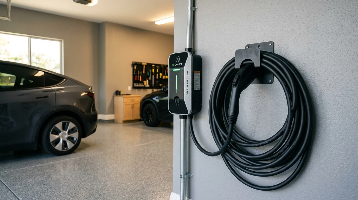
Installing a Level 2 electric vehicle charger in an attached garage with an adjacent electrical panel is straightforward: a short run of 6 AWG copper conductor satisfies standard 48-amp continuous charging requirements. However, residential installations increasingly require extended circuit runs—feeding detached garages, backyard workshops, parking pads, or outbuildings situated 75, 100, or 200 feet away from the main service panel. Over these distances, electrical resistance inside the conductor causes substantial voltage drop.
Under the National Electrical Code (NEC), excessive voltage drop does not merely waste kilowatt-hours as dissipated ambient heat in conduit; it triggers onboard EV charger undervoltage faults, extends charging durations, accelerates insulation thermal degradation, and can overheat terminal connection lugs. In this engineering guide, we examine voltage drop physics, conductor cross-sectional sizing, and copper versus aluminum feeder economics for extended EV charging runs.
- NEC 3% Voltage Drop Rule: NEC Informational Note 210.19(A) recommends that branch circuit conductors be sized so maximum voltage drop does not exceed 3% under full continuous load (7.2V on a 240V nominal circuit).
- Continuous Load Multiplier: Because EV charging operates at 100% capacity for multiple consecutive hours, Article 625 mandates sizing conductors for 125% of rated current (60A breaker and conductors for a 48A charging load).
- Upsizing Boundaries: A 48A EV charger on 6 AWG copper exceeds the 3% voltage drop limit at approximately 75 feet of run length. Runs exceeding 80 feet require upsizing to 4 AWG copper or 2 AWG aluminum to maintain voltage stability.
What Is the Maximum Allowable Voltage Drop for EV Charging Under NEC?
When an EV vehicle begins charging at 48 amps (11.5 kW), that current flows continuously through every foot of the supply conductor and back along the return neutral or phase conductor. The fundamental relationship governing conductor impedance is Ohm’s Law: V_drop = 2 × I × L × R / 1000, where I is current in amps, L is one-way distance in feet, and R is the conductor’s resistance in ohms per 1,000 feet (from NEC Chapter 9, Table 8).
If voltage drops significantly below 230V, modern electric vehicles detect the sag. Modern EV battery management systems (BMS) in Tesla, Hyundai/Kia, and Ford vehicles monitor line voltage continuously. If line sag exceeds 5% to 7%, the vehicle’s onboard inverter autonomously throttles charging current—dropping from 48A down to 32A or 24A to protect against terminal overheating. The homeowner pays for a high-speed 11.5 kW charger but receives sluggish 7.6 kW charging speeds due to inadequate conductor cross-section.
Voltage Drop vs Conductor Gauge for 48A Continuous Charging (240V)
The table below models a 48-amp continuous EV charging load (requiring a 60-amp overcurrent protection device) operating at 240 volts single-phase across varying one-way circuit distances. It demonstrates when conductor upsizing is required to remain within the NEC 3% (7.2V) threshold:
| One-Way Distance | 6 AWG Copper (THHN) | 4 AWG Copper (THHN) | 2 AWG Aluminum (XHHW-2) | Engineering Recommendation |
|---|---|---|---|---|
| 25 Feet (Attached Garage) | 1.18V (0.49%) | 0.74V (0.31%) | 1.25V (0.52%) | Standard 6 AWG Copper is optimal |
| 50 Feet (Basement to Garage) | 2.35V (0.98%) | 1.48V (0.62%) | 2.49V (1.04%) | 6 AWG Copper well within limits |
| 75 Feet (Detached Run 1) | 3.53V (1.47%) | 2.22V (0.93%) | 3.74V (1.56%) | 6 AWG Copper acceptable (<1.5%) |
| 100 Feet (Detached Garage) | 4.70V (1.96%) | 2.96V (1.23%) | 4.99V (2.08%) | Upsize to 4 AWG Cu or 2 AWG Al |
| 150 Feet (Long Conduit Run) | 7.06V (2.94%) | 4.44V (1.85%) | 7.49V (3.12%) | Mandatory 4 AWG Cu or 1/0 Al |
| 200 Feet (Agricultural/Outbuilding) | 9.41V (3.92% – FAILS) | 5.92V (2.47%) | 9.98V (4.16% – FAILS) | Mandatory 2 AWG Cu or 1/0 Al |
As detailed in our analysis of V2H bidirectional charging architectures, sizing conductors conservatively is doubly critical when the circuit must support reverse power flow during home power outages, where line voltage stability protects sensitive residential electronics.
Copper vs Aluminum Feeders: The Cost-Benefit Tradeoff
When running long feeder circuits (100+ feet), the price divergence between copper and aluminum becomes dramatic. A 100-foot run of three 4 AWG copper conductors plus an 8 AWG ground can easily exceed $350 in bare wire costs alone. In contrast, 2-2-2-4 aluminum mobile home feeder (MHE) or direct-burial URD aluminum cable costs roughly $1.10 to $1.40 per foot ($110–$140 total), saving over 60%.
However, running aluminum conductors directly into EV wall connectors introduces a common installation hazard: terminal compatibility. The vast majority of Level 2 EV charging stations (Tesla Universal Wall Connector, ChargePoint Home Flex, Wallbox Pulsar Plus, Emporia) feature terminal lugs rated exclusively for solid or stranded copper conductors. Squeezing an aluminum conductor into a copper-only terminal creates galvanic corrosion and thermal expansion failure.
To safely utilize cost-effective aluminum feeder wire for long detached runs, follow this standard engineering protocol:
- Install a small 60A or 100A subpanel in the detached garage fed by the aluminum conductors. Modern subpanel main lugs and breaker lugs are dual-rated AL9CU (rated for 90°C aluminum or copper).
- From the subpanel breaker, run a short 3-foot to 6-foot whip of 6 AWG copper wire through conduit into the EV charger terminals.
- Alternatively, terminate the aluminum conductors inside an external junction box using dual-rated mechanical pin adapter lugs (e.g., Ilsco Macadapt) or Polaris insulated taps, transitioning cleanly to copper pigtails before entering the EVSE housing.
Conduit Fill and Thermal Derating Considerations
Upsizing conductor gauge to mitigate voltage drop has a direct cascading impact on conduit fill requirements under NEC Chapter 9, Table 1:
- 3/4-inch Schedule 40 PVC Conduit: Maximum allowable 40% fill area is 0.213 sq inches. While three 6 AWG THHN conductors fit easily, three 4 AWG THHN conductors plus an 8 AWG ground exceed this limit, risking severe cable binding during pulls.
- 1-inch Schedule 40 PVC Conduit: Provides 0.333 sq inches of usable area. This is the minimum recommended conduit diameter for any EV run exceeding 75 feet to accommodate 4 AWG copper or 2 AWG aluminum without violating maximum sidewall pulling tension.
- Ambient Temperature Derating (NEC 310.15): In southern climates or sunny attic runs where conduit temperatures exceed 113°F (45°C), ampacity must be multiplied by a thermal correction factor of 0.87. Sizing conductors strictly for 60A without thermal headroom can result in nuisance breaker tripping during summer daytime charging sessions.
For any EV charger installation with a one-way wire path exceeding 80 feet, never install standard 6 AWG copper wire. The accumulated 2.5% to 4% voltage drop will cause continuous thermal stress and prompt vehicle charging throttles. For detached structures over 100 feet away, install a 1-inch or 1-1/4-inch conduit run with 2 AWG aluminum feeder into a local subpanel. You will cut material costs in half while providing rock-solid voltage stability and future-proofing the garage for secondary electrification loads.